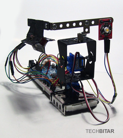
LuxBlaster: Give that rude driver behind you a taste of his high beam (Arduino)LuxBlaster is an Arduino robot that detects and tracks the most intense light source then sends back an intense and annoying light in the same direction.
WARNING: THIS PROJECT IS JUST FOR FUN AND SHOULD NEVER LEAVE THE LAB. This project falls under the category of fun gizmos and is not intended for real world usage. While you are driving at night, every once in a while a car will approach you from behind with its annoying high beam turned on. Some car headlights can be as powerful as 3000 Lumens. Most of the time, the driver of the car will remember to lower the lights. But on rare occasions you will run into a driver who will blast his/her high beams from behind to prod you into shifting to another lane quickly even if you are driving above the speed limit. The smart thing to do is to let this driver pass. But what if the street is crowded or you are on a country road with two narrow lanes. Even if you can't change lanes for a number of reasons, you would turn the rear view mirror up or down to avoid the nasty high beam reflection from behind your car. Some reckless drivers, to intimidate you, will swerve to the left or right to ensure their annoying high beam is reflected into your face via the side mirrors. It's on those occasions that I wished I had the LuxBlaster...but glad I did not. So just for fun, here's the dream gadget that would have given those reckless drivers a taste of their own high-beam. Except that two wrongs could push cars off the road. Keep in mind the LuxBlaster can be annoying at best since the 230 Lumens of the 3W LED is no match for the disorienting power of a single 3000 Lumens xenon headlamp blasted back at you. THE LUXBLASTER HAS GENERATED INTENSE DISCUSSIONS ON ROAD SAFETY ON YOUTUBE, BUT THE QUESTIONS KEEP REPEATING SO I DECIDED IT'S BEST TO HAVE A LUXBLASTER FAQ PAGE ON MY BLOG WITH ANSWERS TO THOSE FREQUENT QUESTIONS. LuxBlaster In The News
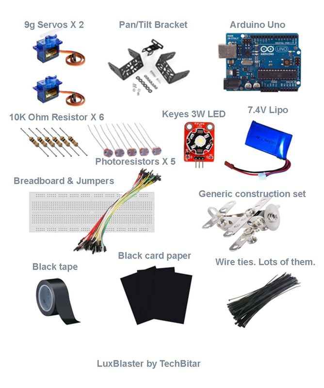
ComponentsHARDWARE
SOFWTARE
Assembling the Pan/Tilt Servo BracketFollow the steps in the diagram to assemble the servos and brackets. The most challenging part of the LuxBlaster is getting the Pan/Tile platform assembled and wired according to this guide to ensure the Arduino code works with no modifications. Once you have the LuxBlaster up and running feel free to make adjustments.
THE PAN/TILT BASE I used a metal base to hold the pan/tilt platform which I found in a cheap construction set. But you can use any other material such as wood if you prefer. What matters is the orientation of the servos, the correct wiring, the centering of servo horns, and the physical stability of the pan/tilt platform. When the servos rotate quickly, they can shake the whole breadboard to the point of dislodging components or forcing them out of alignment. CENTERING THE SERVOS Center then fix the servo horns to the mid point between the rotation start/end before you screw on the brackets. When you run the accompanying Arduino code, in the initialization section the Arduino will issue a command to center servos at 90 degree which is the half way point for both servos. If your servo horns are not physically centered properly, the servos and brackets may assume starting positions at the wrong rotation position and the pan/tilt tracking mechanism will not function properly. TESTING AND DEBUGGING THE SERVOS When it's time to test your wiring against the Arduino code, test the pan servo first then test the tilt servo second, but if you attempt to debug while both servos are active at the same time you will make testing more difficult. Constructing The Light Tracking RadarThere are many ways to design the light tracking radar. But the basic concept is to have 4 quadrants each containing a photoresistor and one middle cavity for the center photoresistor.
We want the photoresistors to be optically isolated from one another but not isolated from the ambient light around them. This isolation makes it possible for the different photoresistors to register different light intensity readings from 5 different directions with the fifth being the center photoresistor. The Arduino code compares the reading of the resistors from the 4 quadrants against the reading of the center photoresistor to determine to what direction it should move the pan/tilt platform to keep the center photoresistor pointing in the direction of the most intense light source. MAKING THE PAPER RADAR I should have used matt black cardboard paper instead of the beige colored paper you see in the diagrams. So I ended up painting most of the exposed areas black and using black electric tape to minimize light reflection. I cut a 20 cm X 5 cm piece of cardboard then folded each 1 cm section over the next 1 cm section until I got an accordion shape. This is just to make the edges more flexible. Then I folded it into a 4-tip star with an open square inside for the center photoresistor. All the sections are 1 cm long. I stapled the folded sections but you can use glue if you prefer. WIRING THE PHOTORESISTORS The photoresistors have long pins so I cut them all down to 1 cm in length. Then I used 2 female-male jumper wires to wire each photoresistors. You can use glue to ensure the connection is solid. Finally I wrapped each photoresistor in black electric tape. There's really no art to this just make sure you have solid connection to avoid unnecessary debugging time. For the center photoresistor, I used a piece of anti-static foam but styrofoam or even a regular sponge would do fine. The point is to fix the photoresistor in the center cavity of the light tracking radar. Putting The LuxBlaster TogetherSince the 3W LED had to point in the same direction as the light tracking radar it made sense for both components to be on one frame but far enough from one another. Any closer, and the light from the 3W LED could contaminate the readings from the light tracking radar photoresistors. For this project, I think I have achieved an acceptable level of isolation between the LED and the photoresistors.
The Keyes 3W LED is a complete circuit with a power FET ready to be controlled from an Arduino. This simplified my LuxBlaster circuit. I used a wire tie to fix the LED module on one end of a construction set frame. For the light tracking radar, I used electric tape to stick one fin to the right-angled section so the photoresistors are pointing in the same direction as the LED. From this point on, remember that the light tracking radar photoresistors should be labeled based on their physical location, from your point of view. This is important because it dictates which Arduino analog pin a given photoresistor should be wired to:
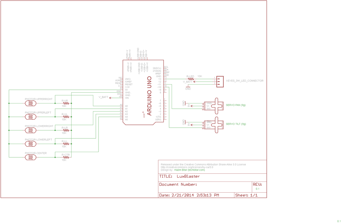
Now fix LED/Radar frame on top of the tilt bracket and proceed to wire the components according to the attached schematic. LuxBlaster SchematicPOWER NETS
In the Eagle schematic note how the two 9g servos are powered directly via the Arduino's 5V power net. But both the Arduino (VIN) and the 3W LED get their power directly from the 7.4V Lipo battery. Yet all GND points must be connected together, which may not be clear for those who did not work with schematics before. PHOTOREISTOR SIGNAL A photoresistor is a variable resistor whose value changes with the amount of light being exposed to. More light translates into less resistance. But Arduino Uno can't measure resistance. It can measure voltage changes from 0 up to 5V. So each photoresistor is wired as the R1 resistor in a voltage divider circuit while a 10K Ohm resistor is the R2 resistor. The joint between R1 and R2 is wired to an Arduino analog pin where changes in voltage due to changes in light intensity are measured and output as an integer numbers between 0 and 1023 (10-bit ADC). The more light hits the photoresistor, the less resistance, the more voltage is read and the higher the number reported by the Arduino analog pin. As to how you interpret the numbers generated by the analog pins, that's totally subjective and depends on your requirements. You may find a 600 value to mean an annoying light is being pointed at you while others may think 800 is really an annoying light intensity and decide to turn on the 3W LED. Calibrate the LuxBlaster by operating it in various lighting conditions then take note of the values generated by the sensors. This will help you decide your thresholds and max/min values. Or, add buttons or pots to control these values during operation. LED SIGNAL The 3W LED module has three pins: GND, VIN, Signal. The VIN is wired to the external battery since this LED draws up to 0.75 Amp. This is more than the Arduino can provide. The signal pin is wired to the famous digital Pin 13 on the Arduino. (Run Arduino Uno with the Blink sample sketch while the 3W LED is connected to get the Mother of all Blinks.) Arduino Code/* PROJECT: LuxBlaster PROGRAMMER: Hazim Bitar (techbitar at gmail dot com) DATE: Feb 22, 2014 FILE: luxblaster.ino LICENSE: Public domain */ #include <Servo.h> #define PIN_SUPER_LED 13 // Pin to connect the star LED #define PIN_PAN_SERVO 11 #define PIN_TILT_SERVO 10 #define TIME_INCREMENT 5 // wait half sec between complete sensor readings #define ERROR_MARGIN 20 // control accurace of reaction to sensor changes // Limit angle of servo rotation to control light sensing/blasting range #define TILT_MAX 120 #define TILT_MIN 30 #define PAN_MAX 130 #define PAN_MIN 20 // how many angles to rotate servo per step #define TILT_INC 5 #define PAN_INC 5 // how strong should the incoming light be before LuxBlaster LED is turned on #define PAIN_LEVEL 700 Servo servoPan; Servo servoTilt; // For debugging, I have commented the servo rotation behavior. // This is how my setup works. If your servos rotate differently, check the wiring. // int posPan =0; // all the way to the left (facing led) // int posPan =180; // all the way to the right (facing led) int posPan =90; // center position // int posTilt = 0; // all the way down // int posTilt = 180; // all the way up int posTilt = 90; // center // the setup routine runs once when you press reset: void setup() { // initialize serial communication at 9600 bits per second: Serial.begin(9600); pinMode(PIN_SUPER_LED, OUTPUT); servoPan.attach(PIN_PAN_SERVO); servoTilt.attach(PIN_TILT_SERVO); // set servos to deafult startup position servoPan.write(posPan); servoTilt.write(posTilt); // blink 3 times for startup diags for (int i=0;i<3;i++){ digitalWrite(PIN_SUPER_LED, HIGH); delay(500); digitalWrite(PIN_SUPER_LED, LOW); delay(500); } } // the loop routine runs over and over again forever: void loop() { // read the input on analog pin 0: int sensorUpperRight = analogRead(A0); int sensorUpperLeft = analogRead(A1); int sensorLowerRight = analogRead(A2); int sensorLowerLeft = analogRead(A3); int sensorCenter = analogRead(A4); int midLeft = (sensorUpperLeft + sensorLowerLeft) * 0.5; // mid left reading int midRight = (sensorUpperRight + sensorLowerRight) * 0.5; // mid right reading int midUpper = (sensorUpperLeft + sensorUpperRight) * 0.5; // mid upper reading int midBottom = (sensorLowerLeft + sensorLowerRight) * 0.5; // mid lower reading if (sensorCenter > PAIN_LEVEL) // if center censor is hit with intense light, turn LED on digitalWrite(PIN_SUPER_LED, HIGH); else digitalWrite(PIN_SUPER_LED, LOW); // if no, turn LED off if (midLeft > sensorCenter) { posPan =- PAN_INC; if (posPan < PAN_MIN) posPan = PAN_MIN; } if (midRight > sensorCenter) { posPan =+ PAN_INC; if (posPan > PAN_MAX) posPan = PAN_MAX; } if (midUpper > sensorCenter) { posTilt =+TILT_INC; if (posTilt > TILT_MAX) posTilt = TILT_MAX; } if (midBottom > sensorCenter) { posTilt=-TILT_INC; if (posTilt < TILT_MIN) posTilt = TILT_MIN; } servoTilt.write(posTilt); servoPan.write(posPan); // List the light sensor values to COM Serial.println("------------------------------"); Serial.println("Upper Right: "+String(sensorUpperRight)); Serial.println("Upper Left: "+String(sensorUpperLeft)); Serial.println("Lower Right: "+String(sensorLowerRight)); Serial.println("Lower Left: "+String(sensorLowerLeft)); Serial.println("Center: "+String(sensorCenter)); delay(TIME_INCREMENT); // delay in between reads for stability } |
- Home
- About
-
Projects
- LuxBlaster
- SensoDuino
- ArduDroid: Simple Bluetooth control for Arduino and Android
- TV Volume Loudness Guard
- Geo Data Logger
- Face Tracking with Arduino and OpenCV
- Kinect Controls Servos Using Human Motion
- Fast Line-following Robot
- BridgeDuino
- Universal IR Remote Control Station for Android
- Bluetooth-controlled Pan-Tilt Servo
- Modify The HC-05 Bluetooth Module Defaults Using AT Commands
- Bluetooth Comm for Arduino and PC
- GOduino: The Breadboard-friendly Robot Controller
- How to Network Many Arduinos with Sensors using I2C
- Your Android Phone Is A Sensors & Comm Nervana
- Blog


